5 volt power supply using LNK584DG IC

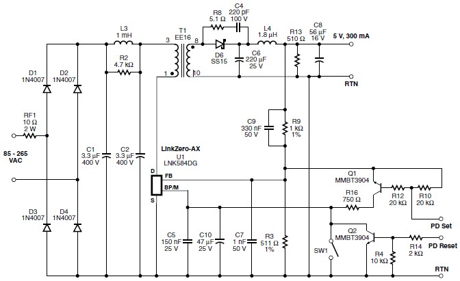
A very simple high efficiency power supply electronic project can be designed using the LNK584DG circuit designed by Power Integrations . The LNK584DG circuit is a very nice IC from LinkZero-AX, that helps you to design a very simple high efficiency switching power supply circuit using few external electronic components . This switching power supply circuit diagram is a typical non-isolated 5 V, 300 mA output auxiliary power supply using LinkZero-AX.
This circuit is typical of auxiliary supplies in white goods where isolation is often not required. AC input differential filtering is accomplished by the π filter formed by C1, C2 and L3. The proprietary frequency jitter feature of the LinkZero-AX eliminates the need for any Y capacitor or common-mode inductor. Wire-wound resistor RF1 is a fusible, flame proof resistor which is used as a fuse as well as to limit inrush current. Wire wound types are recommended for designs that operate >132 VAC to withstand the instantaneous power dissipated when AC is first applied.
The output voltage is directly sensed through feedback resistors R3 and R9, and regulated by LinkZero-AX (U1) via the FEEDBACK pin. Capacitor C7 provides high frequency filtering on the FEEDBACK pin to filter noise and to avoid switching cycle pulse bunching. The controller in U1 receives feedback from the output through feedback resistors R9 and R3.
Based on that feedback, it enables or disables the switching of its integrated MOSFET to maintain output regulation. Switching cycles are skipped once the FEEDBACK pin threshold voltage (1.70 V) is exceeded. When the voltage on the FEEDBACK pin falls below the disable threshold (1.70 V), switching cycles are re-enabled. By adjusting the ratio of enabled to disabled switching cycles the output voltage is regulated. At increased loads, beyond the output peak power point, where all switching cycles are enabled, the FEEDBACK pin voltage begins to reduce as the power supply output voltage falls. Under this condition the switching frequency is also reduced to limit the maximum output overload power.
When the FEEDBACK pin voltage drops below the auto-restart threshold (typically 0.9 V on the FEEDBACK pin), the power supply enters the auto-restart mode. In this mode, the power supply will turn off for approximately 1.2 s and then turn back on for approximately 170 ms. The auto-restart function reduces the average output current during an output short-circuit condition.
As you can see in the circuit diagram , this power supply circuit is very simple an can be powered using a wide range input voltage from 85 up to 265 VAC .
Add new comment