Triangular wave signal generator
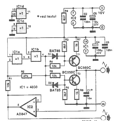
Using this circuit diagram can be a very simple triangular wave signal generator. The circuit is an usual rectangular-triangular oscillator used. A Schmitt trigger converts a triangular wave in one rectangular, used to charge and discharge a capacitor continuously through currernt sources. Positive current source T1 ensure charge and negative current source T2 discharge.
Trigger output alternating commands conduction of T1 and T2. If the output of IClb is logical 1 T2 conduct if is logical 0 T1 conduct.
Rectangular signal amplitude must not be higher than the voltage of T1 and T2. Assuming a supply voltage of 10 V, it follows that the amplitude of the triangular signal is 2.5 Vpp.
Circuit can generate signals with frequencies up to 300 kHz. The value of the scheme, the output frequency is 38 kHz. Frequency can be changed by changing the value of C1.


Add new comment