Light sensitive switch
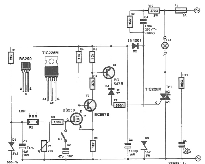
This light sensitive switch is built with transistors and other semiconductor devices. This switch operated light is designed to be connected directly to the voltage network, eliminating the low voltage source.
This circuit turn on a light after dark comes, and disconnects when light comes again.
The switch is powered from the mains through R10, C4, D3. D2 and C3. A reference voltage source, D1, power with 8.2 V measuring light network, R2-P1. At low light intensity, resistance of photoresist (LDR), R2 increases. Therefore, P1 voltage decreases, so will drop and the gate-source voltage of the FET T1. When switch S1 is closed, the time constant R3-C2 causes T1's gate voltage to vary more slowly than resistance R2. This is necessary to prevent rapid reaction to changing circuit ambient light intensity.
When light intensity increases above the set with P1, T1 goes in conduction, so that the load will be disconnected.
Switch S1 is used to disable the time constant during adjustment. R9 resistor serves to discharge C4 after disconnecting from the mains circuit.


Add new comment