Circuit detectors and sensors based electronics projects
Circuit detectors and sensors based electronics projects like: metal detectors circuits, smoke detectors circuit, water detector circuit, light detector and other based sensors projects.
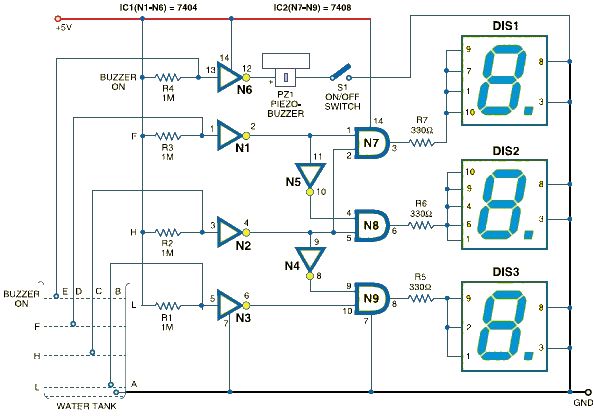
This water level indicator electronic circuit uses a 7-segment display to indicate the water level (low, half and full) in the tank. This water level indicator electronic circuit is based on the 7408 quad two inputs and gates IC (that contains four input independent gates) and a 7404 hex inverting gates IC.
When the tank is full a buzzer is used to alert you of water overflowing from the tank.
This water level indicator electronic circuit shows the water level by displaying L, H and F for low, half and full, respectively.
The circuit uses five level sensors to sense the different water levels ( one for common GND, one for low, one for high one for half and one for overflow ) .
A high voltage at the input pin of the NOT gate, it outputs a low voltage . For a low voltage at the input pin of the NOT gate, it outputs a high voltage.
When the tank is empty, the input pins of IC 7404 are pulled high via a 1-mega-ohm resistor.
When the water is at the low sensor the common cathode 7 segments DISP3 shows ‘L’ indicating low level of water in the tank.
When the water is at the half sensor the common cathode 7 segments DISP2 shows ‘H’ indicating half level of water in the tank.
When the water is at the low sensor the common cathode 7 segments DISP1 shows ‘F’ indicating that the tank is full.
When water is at the overflow sensor ( buzzer sensor ) the pin 13 of gate N6 goes
low to make output pin 12 and the buzzer will sound .
All water sensors must be constructed from noncorrosive material . For powering this electronic circuit you must to use a regulated 5V to power the circuit.
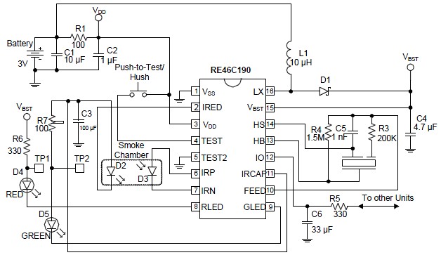
Using this photoelectric smoke detector circuit can be designed a very simple and low power smoke detector alarm project that is based on the RE46C190 smoke detector IC .
With minimal external components, this smoke detectors alarm circuit will provide all the
required features for a photoelectric smoke detector type electronic project .The design incorporates a gain-selectable photo amplifier for use with an infrared emitter detector pair.
An internal oscillator strobes power to the smoke detection circuitry every 10 seconds, to keep the standby current to a minimum. If smoke is sensed, the detection rate is increased to verify an Alarm condition.
This photoelectric smoke detector circuit type smoke detector alarm will check for a low battery condition every 86 seconds, and chamber integrity is tested once every 43 seconds, when in Standby. The temporal horn pattern supports the NFPA 72 emergency evacuation signal.
Pin nr 12 us an interconnect pin that allows multiple detectors to be connected such that, when one unit alarms, all units will sound (using pin 12 pin you can create a smoke detector alarm circuit for many rooms ).
Utilizing low power CMOS technology, the RE46C190 was designed for use in smoke detectors that comply with Underwriters Laboratory Specification UL217 and UL268.
This smoke detector circuit project require a 3 volt DC power supply circuit , you can also use a simple 3 volt battery ( because it has a very low power consumption ) .
C2 should be located as close as possible to the device power pins, and C1 should be located as close as possible to VSS.
Schottky diode D1 must have a maximum peak current rating of at least 1.5A (for best results it should have forward voltage specification of less than 0.5V at 1A, and low reverse leakage) and L1 inductor must have a maximum peak current rating of at least 1.5A.
Using the LM35 temperature sensor we can design various electronic thermometer projects that require a temperature sensor . The LM35 series are precision integrated-circuit temperature sensors, whose output voltage is linearly proportional to the Celsius (Centigrade) temperature.
The LM35 electronic thermometer does not require any external calibration or trimming to provide typical accuracies of ±1⁄4°C at room temperature and ±3⁄4°C over a full −55 to +150°C temperature range.
Combining two simple low cost integrated circuits LM35 ( temperature sensor) and LM3914 dot / bar display driver , can be designed a very simple low cost and high efficiency LED temperature measurement system .
The LM35’s low output impedance, linear output, and precise inherent calibration make interfacing to readout or control circuitry especially easy. It can be used with single power supplies, or with plus and minus supplies. As it draws only 60 μA from its supply, it has very low self-heating, less than 0.1°C in still air.
As you can see in the circuit diagram , this bargraph thermometer require few external components and .